The FRP Cable Support Systems is most suitable where the metallic Systems gets Corroded (Iron gets rusted and Alluminium develops White or Silver grey Patina)
The Causes Of Corrosive Attack Are :-
| Simple Chemical Attack :- | When The Environment Is Loaded With Chemical Vapours, The Attack Is Severe. |
| Simple Chemical Corrosion :- | |
| Chlorine Contents :- | In Atmospheric Air (Coastal / Sea) |
In any event the Metallic System Has Limited Service Life / Expectancy (Regardless Of How The End Point In Defined)
Designed To Withstand Corrosion And Stresses.
The Main Features Are :
Material of construction :-
Main Ingredients :
Pultrusion is a manufacturing process for producing continuous length of reinforced plastic structural shapes.
The process involves pulling of Continuous Glass Fibres, Continuous Glass Fibre Mat, Plastic fibre veil through a liquid resin bath. The glass fibre gets impregnated by the resin mixture and this impregnated fibre is pulled through a heated steel shaping die, where the resin gets GEL and the SOLID CONTINUOUS PROFILE comes out of the die.
The continuous Glass Roving give the strength in the longitudinal direction, where as Glass Mat gives the strength in the transverse direction.
The type of Resin to be used depends upon the environment where the cable support System is to be used.
| For General Environment :- | ISO PHATHALIC GRADE |
| For Severe Corrosive Environment (Caustic and strong acidic) :- |
VINYLESTER |
The Resin is (FIRE RETARDANT & U. V. STABILISED)
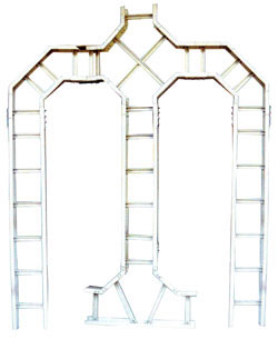
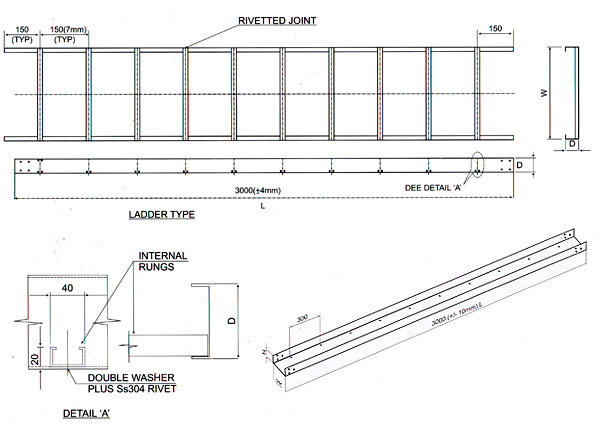
Types Of Cable Trays :-
| Ladder Type | |
|---|---|
| It Is A Structure Consisting Of Two Longitudinal Side Members Connected By Individual Transverse Members Called Rung. The Longitudinal Members Are C-Channel |
 |
| The Rungs are specially designed to | |
|---|---|
| Withstand the load Allow the cable to dropout without contacting a sharp edge. Double inside fold is used to anchor the fastener head for clamping the Cables. |
 |
Joining Of Transverse & Longitudinal Members :-
Perforated Type :-
It is a structure consisting of bottom (ventilated or solid) with the longitudinal siderails. (Perforations are made by drilling holes)
Matching Accessories :-
The Following accessories are generally used to complete the system :
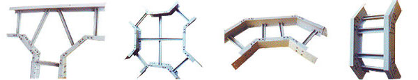
Notes :- All CUT or Machined Edges, Holes & Abrasions Must be Sealed with Resin
Installation :-
| General :- | The cable Trays and Accessories are bolted together and fixed to Supporting member. For the purpose of bolting together the side rails and all accessories have holes on each end for fixing Connector plates. |
| Support Span :- | Recommended Support Span at installation site must not exceed 2000. |
| Cable Fill :- | Recommended cable fill should not normally be more than 80% of the inside area of the cable tray. |
Loading Capacity :-
The Working load capacity represents the ability of a cable tray to support the weight of the cable and the following guidelines should be Considered for loading the trays.
With the Support span not exceeding 2000 mm, the maximum designed loading is UDL + 70 kg. Concentrated Load at the Centre of the Span :
| U. D. L. (Cable Load) | Width |
|---|---|
| 30 kg / linear mtr | 150 mm |
| 60 kg / linear mtr | 300 mm |
| 90 kg / linear mtr | 600 mm |
| 120 kg / linear mtr | 750 mm |
We are one of the leading Exporter, Supplier & Manufacturer in Mumbai India of FRP Cable Trays